Toyota Maf Sensor Wiring Diagram

Detroit Ddec 4 Ecm Wiring Diagram, How to start a Series 60 Detroit Swap Mawk wiring 12.7 14L DDEC IV, 3.78 MB, 02:45, 32,122, Bob Brenner, 2019-03-14T23:37:55.000000Z, 19, Ddec Iv Ecm Wiring Diagram, schematron.org, 5100 x 3300, png, ddec ecm schematic diesel lt9500 freightliner schematics cableado injector justanswer celect amp3 6v92 fuse floraoflangkawi, 20, detroit-ddec-4-ecm-wiring-diagram, Anime Arts
How to fix toyota corolla gli/xli 2006 maf sensor wiring diagrams solved | sabri efi auto electrician |the map sensor calculates the air of the car. As a result, the current flows from terminal 4 of the light failure sensor to terminal 11 to ground and turns the rear lights verifying the map sensor has power. There are different types of mass air flow sensors. Wiring diagram for code 33 map sensor circuit.
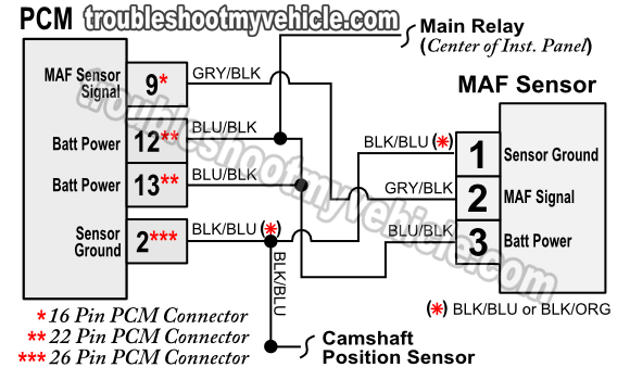
The ecm uses this information to determine the fuel injection time and to provide appropriate airfuel ratio. 2 inspect mass air flow meter (power source voltage) (a) disconnect the m6 mass. Hot power wire (reference voltage comes from the ecu) ground wire signal wire (gives signals to the ecu) the hot wire is a feed power source that is taken from the car computer (ecu). Toyota passenger and sports car forums. Akfahad · old solaraguy user '99 solara joined apr 24, 2007 · 136 posts. Discussion starter · #1 · jun. Particularly what each wire on the maf sensor represents? Toyota maf sensor wiring diagram wiring diagram schemas from wiringschemas. blogspot. com. 2jz maf sensor wiring diagram schematron. org.
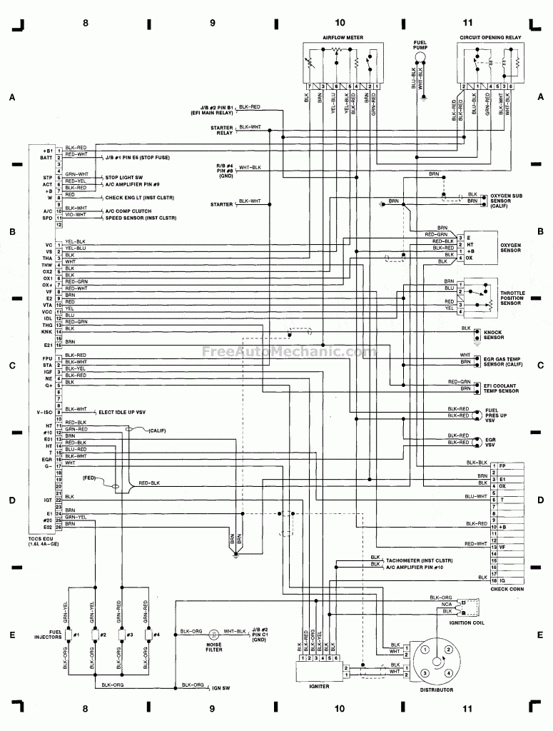
MAF Sensor wiring diagram 1990 Toyota Corolla GTS - FreeAutoMechanic Advice

[DIAGRAM] Toyota Maf Sensor Wiring Diagram FULL Version HD Quality Wiring Diagram - KANDIAGRAMX5
![Toyota Maf Sensor Wiring Diagram [DIAGRAM] Toyota Maf Sensor Wiring Diagram FULL Version HD Quality Wiring Diagram - KANDIAGRAMX5](https://ww2.justanswer.com/uploads/fordguy4u/2012-05-07_125306_a1.jpg)
On a 2005 Toyota Camry 4cyl. is the MAF sensor and the ATS sensor wired together in one 5 wire

Toyota Maf Sensor Wiring | Wiring Diagram Database

Toyota Maf Sensor Wiring Diagram - Wiring Diagram Schemas
Toyota Mass Air Flow Sensor Wiring Diagram - Style Guru: Fashion, Glitz, Glamour, Style unplugged
2jz Maf Sensor Wiring Diagram
[DIAGRAM] Toyota Maf Sensor Wiring Diagram FULL Version HD Quality Wiring Diagram - KANDIAGRAMX5
![Toyota Maf Sensor Wiring Diagram [DIAGRAM] Toyota Maf Sensor Wiring Diagram FULL Version HD Quality Wiring Diagram - KANDIAGRAMX5](https://ww2.justanswer.com/uploads/tracker40/2011-08-06_164804_1.gif)
IAT Sensor Performance Chip Installation Procedure: 2001-2012 Toyota Tacoma Iat sensor/maf

Toyota Mass Air Flow Sensor Wiring Diagram - Style Guru: Fashion, Glitz, Glamour, Style unplugged

